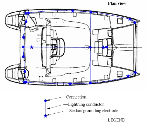
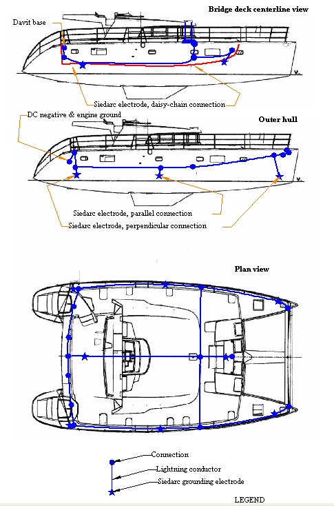
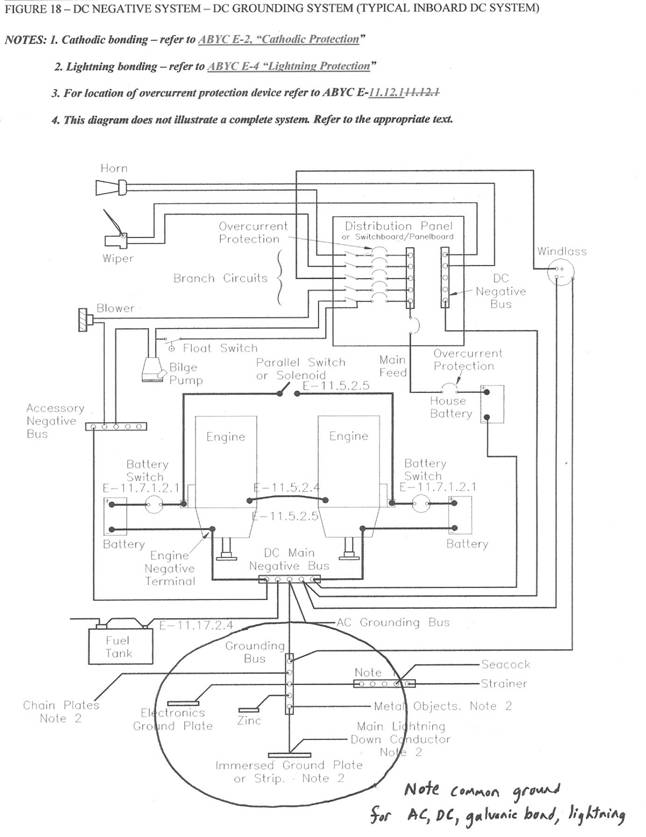
Guidelines for Lightning System on S/V Xela1 System overviewThe lightning protection system comprises an interconnected network of air terminals, conductors, and grounding electrodes that form a conducting grid outside the interior space of the vessel. The protective zone provided by the air terminal at masthead covers all of the boat. Additional air terminals are placed aft of the solar panels to lower the risk of discharges from the solar panels. Down conductors are routed externally to all wiring, plumbing and occupied regions. A conducting grid comprises a loop conductor on the outside of each hull, interconnections across the vessel connecting the base of the compression post, and the aluminum bow cross support. The bimini support is connected to this loop. Grounding is provided via six Siedarc electrodes distributed around the hull, two Siedarc electrodes below the bridge deck, and the existing sail drives. All Siedarc electrodes are installed above and near the waterline.Major features are summarized in the diagrams in Appendices 1. Appendix 2 is a copy of Figure 18 from ABYC Standard E-11 showing a common connection for DC ground, AC ground, cathodic bonding ground, and lightning bonding ground. Appendix 3 gives instructions for lug terminations. 2 Materials & instructions2.1 Materials & instructions to be supplied by customerThe customer will supply the following components in the lightning protection system:
2.2 Materials to be supplied by vendorThe vendor will supply the following materials:
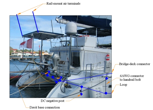
3 Air terminals3.1 MaterialsThe air terminals comprise a 1/2 " diameter solid aluminum rod with a 1/2-13 threaded base that is attached to an "L" bracket at the mast head, and two rail-mounted air terminals on the solar panel support as shown in Figure 4-3.3.2 AttachmentThe air terminal is secured to an aluminum 'L" bracket that is secured to the port side of the mast (opposite side to the VHF antenna) at the mast head by means of the 1/2-13 thread on the bottom of the rod. The two rail-mount air terminals are secured directly onto the solar panel supports, either vertical or horizontal. Once secured, each solar-panel air terminal should be tilted up to 20 degrees from the vertical in an outboard direction.4 Loop conductor4.1 OverviewAppendix 1 shows all components of the system. The plan view is shown in Figure 4-1 below. The loop conductor around the boat comprises the forward aluminum support, a conductor down the outside of each hull, a cross connection to the mast support, and a cross connection aft of the main cabin. Figure 4-1 Plan view of loop conductor 4.2 Bow viewAn illustration of the loop conductor at the bow is shown in Figure 4-2, where all lightning conductors are inside the boat. The loop conductor is constructed predominantly from either 1' x 1/16" tinned copper strip, or 2AWG cable , or a combination. The routing of the cross connection from the mast to the outside loop is inside the ceiling liner.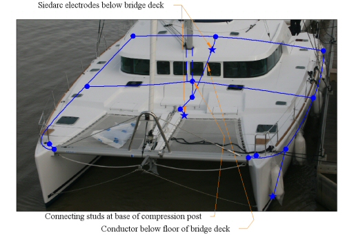 Figure 4-2 Loop conductor layout 4.3 Aft viewFigure 4-3 shows the aft section of the loop. Owing to the number of connections on the cross connection at the stern, tinned copper strip may be preferable to 2AWG cable. See Section 6 for more details concerning connections.
5 Main conductors5.1 Mast & compression postThe mast and compression post are used as main down conductors from the air terminal to the base of the compression post. A 4" tinned brass bolt is screwed through the base of he compression post to continue the connection below, as shown in Figure 6-1.5.2 Loop- grounding conductorsAppendix 1 shows suitable paths for lightning down conductors. All down conductors should be made from either 1" tinned copper strip or insulated 2 AWG tinned copper battery cable terminated with the heavy duty lugs supplied by customer (see Appendix 3 for termination details), or a combination. In general, the preferred route is the most direct path between connecting points with all direction changes by means of as smooth a curve (large radius of curvature) as possible. However, right angled connections between different conductors are acceptable if unavoidable. See the Grounding electrodes section for more details.5.3 Use of metallic fittingsThe aluminum cross support at the bow is used as part of the loop conductor. Details of the connection to this are given in Section 6.1. Otherwise conducting fittings are not used as part of the main loop but are bonded to the closest connection point in the lightning protection system via 6AWG cable. In particular, the following fittings should be bonded: bow pulpits, stern pulpits, and hard top support (via the davit-base connectio to the aft loop).5.4 Down conductors to electrodes and grounding stripsAll connections to grounding strips and Siedarc electrodes are to be made from 2AWG marine-grade insulated battery cable. This cable is already supplied with any electrodes that have a perpendicular connection. These cables may be lengthened by using a 2-way splice to 2 AWG cable.6 Connections6.1 Aluminum cross supportThe 1/2" stainless bolt attaching the forward aluminum cross support to the hull is adequate for the connection to the loop conductor. Use a 1-2 AWG heavy duty lug with a 1/2" hole crimped to 2 AWG insulated tinned copper marine battery cable.6.2 Base of compression postThe compression post sits on top of a fiberglass support as shown in Figure 6-1. Tap a 3/6-16 threaded hole through both the base of the compression post and the fiberglass support, and screw through the 4" tinned brass bolt provided. On its underside, place a tinned brass washer, followed by the 1/2" hex nut, terminating lugs from the connecting cables, and then the washer, split washer and jam nut. The connections at this point are the amidships cross connection and a short cable down to a three-way splice a forward electrode towards the windlass, and an aft connection towards the aft electrode and aft cross connection. Routing the connecting conductors forward and beneath the electrical equipment located nearby provides a shielding grid around the equipment.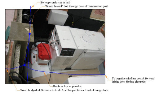 Figure 6-1 Connections at compression post base The forward connection terminates in the negative DC post for the windlass, which also acts as the terminal connecting point for the forward bridge-deck electrode. 6.3 Lug-cableAll lugs are intended for 2AWG cable and have a 3/8" diameter hole. (NOTE: An exception is the lugs that come attached to the daisy-chain Siedarc electrode below the aft bridge deck, which has a ¼" hole). The manufacturer's directions for connecting cable to lug are included in Appendix 3. For better electrical continuity, 0.1-0.3 ml of PenetroxE joint compound should be injected into each lug before inserting the stripped cable. Also, application of heat shrink (with a 1.5" cable overlap) is highly recommended to improve resilience and further impede moisture intrusion. Penetrox E should also be applied between surfaces that are to be connected before attachment.6.4 Bonding to stainless fittingsThe existing stainless screws can be used for minor bonding connections (for example, to the handrails) but these do not meet existing standards and should not be used if the fitting is used as a loop conductor or down conductor.6.5 Tinned copper strip to tinned copper stripIf any tinned copper strip is used as a loop conductor, drill a 3/8" hole through the two strips and through bolt preferable with tinned brass hardware, although stainless hardware is suitable for locations that are not exposed to a damp environment. Apply Penetrox E between mating surfaces. See Figure 6-2.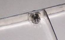
Figure 6-2 Connection between strips 6.6 Standoff studUse a ½" standoff stud for superior connections to the main loop wherever this is tinned copper strip. Drill a 3/8" diameter hole through the aluminum strip, insert the tinned brass bolt through the strip, and then screw on the ½" stud. Connections can then be made directly onto the threaded stud.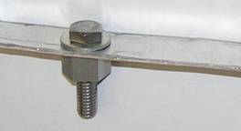 Figure 6-3 Tinned brass stud mounted on tinned copper strip 6.7 Splices between tinned copper cablesSplices between cables can be made by terminating each cable in a lug at the point of the splice, stacking the lugs together and securing with a through bolt and nut. When splicing into a main down conductor, assure that the down conductor lugs are at 180 degrees and the lug on the spliced cable is angled down as much as possible to avoid U-shaped loops. Cover all splices with wet-type heat shrink or waterproof tape.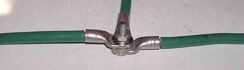 Figure 6-4 Splice connection using lugs and cable 7 Grounding electrodes7.1 Siedarc electrodes in through-hull fittingsElectrode positioning is illustrated in Appendix 1 and Figure 7-1 below.. Generally, each electrode should be installed above the stationary waterline and below the lowest flange of any nearby plumbing through hulls. Each electrode cable is attached to the loop conductor by the shortest path possible. All Siedarc electrodes are embedded in mushroom-head through-hull fittings.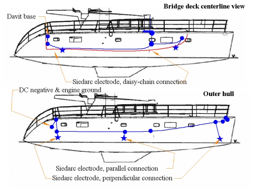 Figure 7-1 Siedarc electrode placement and types See Installation Instructions for Siedarc electrodes for further installation details. 7.2 Immersed grounding conductorThe sail drives are used as immersed grounding surfaces. These are tied into the lightning system using existing DC ground connection post, which is connected to the aft part of the loop conductor using a three-way splice, as shown in Figure 4-3 above.8 Surge suppressors8.1 Antenna coaxAny antenna is at risk of damage even if it is inside the protective zone. While it is impractical to ensure the survival of the antenna itself, protective measures are highly recommended to reduce the likelihood of damage caused by the voltage surge. As a precaution, a transient voltage surge suppressor (TVSS) should be installed in each antenna coax as close as possible to the point where the coax leaves the mast Connect the grounding lug of the TVSS to the closest connecting stud in the lightning protection system and place at least two tight coils in the coax on the other side of the TVSS. Surge suppressors with flange or bulkhead type mounts can be attached directly to any flat conductor (preferably tinned copper strip) that is connected to the lightning system. The most convenient place for this connection is probably the bottom of the 4" bolt through the base of the mast compression post. Polyphaser is a reputable manufacturer. Suitable flange-mount or bulkhead-mount surge suppressors can be purchased from DX Engineering.9. NoticeThe lightning protection system described in this document is fundamentally consistent with Chapter 8 in the National Fire Protection Association Standard NFPA780-2008. Any departures are considered by the author to be improvements over this revised standard. In general, lightning protection systems are limited by the current state of knowledge and no implication is intended that this, or any, protection system will prevent damage or injury.Appendix 1 Component layout
Appendix 2 Figure 18 from ABYC E-11 2003
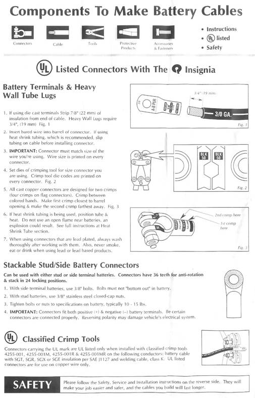
Appendix 3 Termination directions for heavy duty lugs
|
Contact
Marine Lightning Protection Inc.3215 NW 17th StreetGainesville Florida 32605 |
 |
Phone: +1 352 373-3485
Email: info@marinelightning.com URL: www.marinelightning.com
|
|
Please call or email if you have any questions.